Zdenduino - Wi-Fi Testing - Part 3
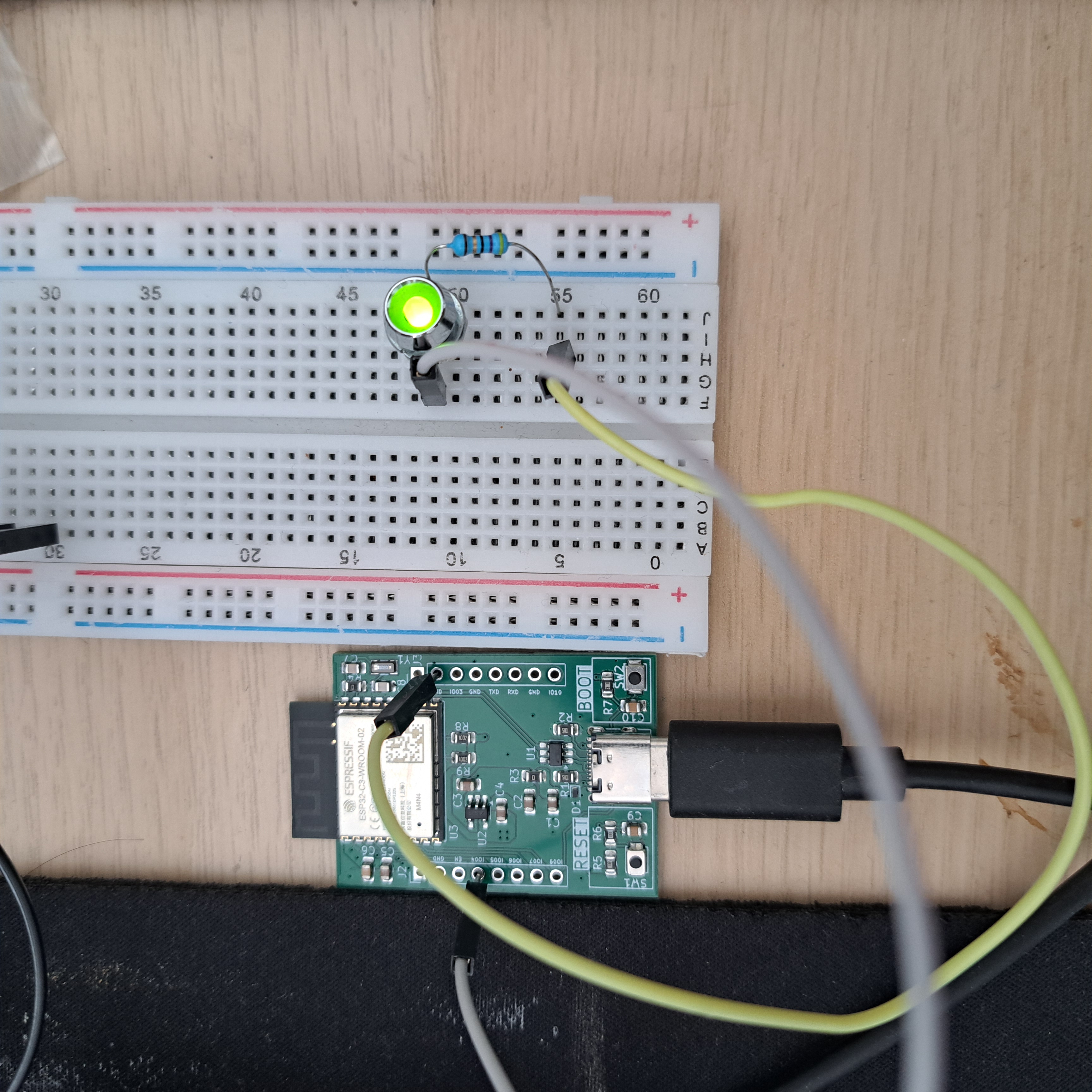
From Blinking Pins to a Real Dev Board
In Part 2, Zdenduino finally crossed the most important line:
It worked.
USB upload worked. GPIO worked. The board did not immediately become a very small and expensive paperweight.
That was a huge relief, but let’s be honest: blinking pins with a multimeter is only the embedded equivalent of a baby saying its first word. Adorable, emotional, important… but not exactly a full conversation yet.
So for Part 3, I wanted to move one step further.
This time the goal was simple:
Test whether Zdenduino behaves like a useful Wi-Fi development board.
No shields yet. No Revision 1 redesign. No big architecture dreams.
Just the board, USB cable, Arduino IDE, Wi-Fi, and a few carefully chosen tests.
I also have to be honest about the code in this article: the test sketches were written with heavy help from AI, mostly ChatGPT/Codex. I knew what I wanted to test, I understood the pieces, and I reviewed the result, but I absolutely did not sit there heroically typing every line from memory. This project is about learning and validating hardware, not pretending autocomplete does not exist.
The Test Plan
The ESP32-C3-WROOM-02 is a surprisingly capable little module. It gives us:
- 2.4 GHz Wi-Fi
- Bluetooth LE 5
- USB CDC/JTAG
- GPIO
- ADC
- PWM
- SPI, I2C and UART
- Deep sleep
- OTA updates
- RISC-V CPU core
That is a lot to test.
The nice thing is that this is not my first ESP32 web experiment. In the Mark0 weather station project, I already went through the whole dance of getting an ESP32 to send data over Wi-Fi, feeding a Flask + SocketIO dashboard, debugging LAN versus Wi-Fi weirdness, and thinking about sensor data as something that should be visible in a browser instead of only printed to Serial Monitor. Mark1 pushed that further with a much tighter GPIO budget, more modules, I2C sensors, display planning, battery thoughts, and the very practical lesson of keeping the Wi-Fi/BLE antenna at the edge of the PCB.
So this test is not starting from zero. Zdenduino is where that previous experience comes back in a cleaner form: instead of plugging an ESP32 DevKit into my own board, I am now testing a board where the ESP32-C3 module is the design.
Actually, it is probably too much for one article. If I tried to test Wi-Fi, BLE, ADC, PWM, OTA, SoftAP, MQTT, sleep modes and every bus interface in one post, this would stop being a blog article and become a small embedded systems textbook.
So I narrowed Part 3 down to the most satisfying first Wi-Fi milestone:
- Scan nearby Wi-Fi networks
- Connect to my home Wi-Fi
- Run a tiny HTTP server
- Control a GPIO pin from a browser
- Show a few live status values
In other words:
Can I open Zdenduino in a web browser and make it do something?
That is the kind of test that feels properly futuristic, even though it is technically just a few hundred lines of microcontroller code yelling over TCP.
Test 1: Wi-Fi Scanner
Before building any kind of web UI, I wanted to verify that the radio side of the module actually works.
The easiest way to do that is a Wi-Fi scanner.
No router credentials. No webserver. No HTML. Just ask the ESP32-C3 what networks it can see and print the result to Serial Monitor.
This is one of those places where AI is honestly very useful: generate a tiny known-good Arduino sketch, upload it, and focus on what the hardware does. Something like this:
1
2
3
4
5
6
7
8
9
10
11
12
13
14
15
16
17
18
19
20
21
22
23
24
25
26
27
28
29
30
31
32
33
34
#include <WiFi.h>

void setup() {
  Serial.begin(115200);
  delay(1000);

  Serial.println("Scanning Wi-Fi networks...");
  WiFi.mode(WIFI_STA);
  WiFi.disconnect();
  delay(100);
}

void loop() {
  int networkCount = WiFi.scanNetworks();

  if (networkCount == 0) {
    Serial.println("No networks found.");
  } else {
    Serial.printf("Found %d networks:\n", networkCount);

    for (int i = 0; i < networkCount; i++) {
      Serial.printf(
        "%2d: %-32s RSSI: %4d dBm  Channel: %2d\n",
        i + 1,
        WiFi.SSID(i).c_str(),
        WiFi.RSSI(i),
        WiFi.channel(i)
      );
    }
  }

  Serial.println();
  delay(5000);
}
This test checks a surprising amount of stuff:
- The ESP32-C3 boots correctly
- The Wi-Fi stack initializes
- The antenna path is not completely broken
- Serial output still behaves as expected
- The module can see real RF traffic around it
And it is also one of those beautifully boring tests where boring is exactly what you want.
There was one small Arduino IDE moment, because of course there was. At first, I did not get the serial output the way I expected. The fix was simple:
Tools -> USB CDC On Boot -> Enabled
After that, Serial Monitor behaved properly and the scanner started printing results.
Here is the output, with the real Wi-Fi names censored for security and privacy reasons. SSIDs can leak more location and device information than people usually expect, so publishing the raw scan felt unnecessary.
1
2
3
4
5
6
7
8
9
10
11
12
Found 11 networks:
 1: Home_WiFi                        RSSI:  -46 dBm  Channel: 12
 2: Neighbor_Network_1               RSSI:  -52 dBm  Channel:  1
 3: Neighbor_Network_2               RSSI:  -61 dBm  Channel:  1
 4: IoT_Device_1                     RSSI:  -63 dBm  Channel:  1
 5: ISP_Router                       RSSI:  -77 dBm  Channel: 13
 6: Wireless_Printer                 RSSI:  -79 dBm  Channel:  6
 7: Neighbor_Network_3               RSSI:  -80 dBm  Channel:  4
 8: Neighbor_Network_4               RSSI:  -83 dBm  Channel: 10
 9: Neighbor_Network_5               RSSI:  -91 dBm  Channel:  4
10: Smart_Device_1                   RSSI:  -92 dBm  Channel: 11
11: Smart_Device_2                   RSSI:  -93 dBm  Channel: 11
If the output lists nearby networks, the board is alive in a much more interesting way than before.
Test 2: Connecting to Wi-Fi
After scanning worked, the next step was connecting to an actual network.
This is where Zdenduino stops being just a USB-connected microcontroller and starts becoming a network device.
1
2
3
4
5
6
7
8
9
10
11
12
13
14
15
16
17
18
19
20
21
22
23
24
25
26
27
#include <WiFi.h>

const char* ssid = "YOUR_WIFI_NAME";
const char* password = "YOUR_WIFI_PASSWORD";

void setup() {
  Serial.begin(115200);
  delay(1000);

  Serial.printf("Connecting to %s", ssid);

  WiFi.mode(WIFI_STA);
  WiFi.begin(ssid, password);

  while (WiFi.status() != WL_CONNECTED) {
    delay(500);
    Serial.print(".");
  }

  Serial.println();
  Serial.println("Connected!");
  Serial.print("IP address: ");
  Serial.println(WiFi.localIP());
}

void loop() {
}
Once the board prints an IP address, the whole project suddenly feels different. And print it does!
1
2
3
Connecting to Home-WiFi........
Connected!
IP address: 192.168.XXX.XXX
Until now, I was uploading firmware, pressing reset, measuring pins, and watching serial logs.
Now the board exists on the network.
That is such a small technical step, but it changes the emotional status of the project completely. This is no longer “my PCB can toggle pins”. This is now “my PCB can join the same network as my laptop and phone”.
That is very cool.
Test 3: A Tiny Webserver
The next obvious step was a small HTTP server.
This is also where I leaned on ChatGPT/Codex the most. I could write a basic webserver by hand, but for a bring-up article I cared more about testing the board than polishing embedded HTML strings. So I asked AI for a compact ESP32-C3 Arduino webserver sketch, reviewed the structure, adjusted the pin, and used it as a test harness.
The plan:
- Connect Zdenduino to Wi-Fi
- Print its IP address
- Open that IP address in a browser
- Show a simple web page
- Add buttons for GPIO control
For testing, I used one GPIO pin as an output. In the future this can drive an LED, relay, MOSFET, optocoupler, or whatever kind of little embedded chaos is appropriate at the time.
For this test, I connected an LED and used the web buttons to switch the GPIO on and off. Watching the browser state change and the LED blink on the actual board is exactly the kind of tiny feedback loop that makes embedded projects feel real.
1
2
3
4
5
6
7
8
9
10
11
12
13
14
15
#include <WiFi.h>
#include <WebServer.h>

const int outputPin = 4;
bool outputState = false;

WebServer server(80);

void handleRoot() {
  server.send(200, "text/html", page());
}

void loop() {
  server.handleClient();
}
Full webserver test sketch
1
2
3
4
5
6
7
8
9
10
11
12
13
14
15
16
17
18
19
20
21
22
23
24
25
26
27
28
29
30
31
32
33
34
35
36
37
38
39
40
41
42
43
44
45
46
47
48
49
50
51
52
53
54
55
56
57
58
59
60
61
62
63
64
65
66
67
68
69
70
71
72
73
74
75
76
77
78
79
80
81
82
83
84
85
86
#include <WiFi.h>
#include <WebServer.h>

const char* ssid = "YOUR_WIFI_NAME";
const char* password = "YOUR_WIFI_PASSWORD";

const int outputPin = 4;
bool outputState = false;

WebServer server(80);

String page() {
  String html;

  html += "<!doctype html><html><head>";
  html += "<meta name='viewport' content='width=device-width, initial-scale=1'>";
  html += "<title>Zdenduino</title>";
  html += "<style>";
  html += "body{font-family:system-ui;margin:2rem;max-width:42rem}";
  html += "button{font-size:1.2rem;padding:.7rem 1rem;margin-right:.5rem}";
  html += "code{background:#eee;padding:.15rem .35rem;border-radius:.25rem}";
  html += "</style></head><body>";
  html += "<h1>Zdenduino</h1>";
  html += "<p>GPIO 4 is currently <code>";
  html += outputState ? "ON" : "OFF";
  html += "</code></p>";
  html += "<p><a href='/on'><button>ON</button></a>";
  html += "<a href='/off'><button>OFF</button></a></p>";
  html += "<p>RSSI: ";
  html += WiFi.RSSI();
  html += " dBm</p>";
  html += "<p>Uptime: ";
  html += millis() / 1000;
  html += " seconds</p>";
  html += "</body></html>";

  return html;
}

void handleRoot() {
  server.send(200, "text/html", page());
}

void handleOn() {
  outputState = true;
  digitalWrite(outputPin, HIGH);
  server.sendHeader("Location", "/");
  server.send(303);
}

void handleOff() {
  outputState = false;
  digitalWrite(outputPin, LOW);
  server.sendHeader("Location", "/");
  server.send(303);
}

void setup() {
  pinMode(outputPin, OUTPUT);
  digitalWrite(outputPin, LOW);

  Serial.begin(115200);
  delay(1000);

  WiFi.mode(WIFI_STA);
  WiFi.begin(ssid, password);

  Serial.print("Connecting");
  while (WiFi.status() != WL_CONNECTED) {
    delay(500);
    Serial.print(".");
  }

  Serial.println();
  Serial.print("Open http://");
  Serial.println(WiFi.localIP());

  server.on("/", handleRoot);
  server.on("/on", handleOn);
  server.on("/off", handleOff);
  server.begin();
}

void loop() {
  server.handleClient();
}
This is not beautiful production firmware, and it is definitely not sacred handwritten code. It is a practical AI-assisted test sketch.
It is not supposed to be more than that.
It is a bring-up test, and as a bring-up test it is perfect. It tests Wi-Fi, TCP/IP, HTTP, GPIO, basic state handling, and the very important psychological feature of clicking a button in a browser and seeing your own hardware respond.
That feature is not listed in any datasheet, but it absolutely should be.
The First Browser Moment
Opening the board’s IP address in a browser felt weirdly satisfying.
There was no cloud. No framework. No app. No server somewhere else.
Just a tiny PCB on my desk serving a page directly from an ESP32-C3.
The page showed:
- GPIO state
- ON/OFF buttons
- Wi-Fi signal strength
- Uptime
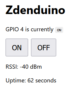
That is already enough to call it a tiny dashboard.
And more importantly, it proves that Zdenduino is not only electrically alive. It can actually become an interface.
That distinction matters.
A blinking LED says:
“The chip runs code.”
A browser-controlled GPIO says:
“This board can become a tool.”
What This Test Proved
After these tests, I am much more confident about the current revision.
So far, Zdenduino can:
- Upload firmware over USB
- Boot and run Arduino sketches
- Toggle GPIO pins
- Scan nearby Wi-Fi networks
- Connect to a Wi-Fi router
- Run a basic HTTP server
- Control an output from a browser
- Report simple status values
That is a pretty solid start for a first custom ESP32-C3 board.
The most important part is that there were no mysterious RF problems, no obvious USB instability during these tests, and no “why is the chip hot?” kind of drama.
I will happily accept that.
Still Not Tested
There is still a long list of things I want to verify:
- PWM
- ADC
- I2C
- SPI
- UART
- Bluetooth LE
- SoftAP mode
- OTA updates
- Deep sleep current
- Long-running Wi-Fi stability
But those deserve proper attention.
Trying to cram all of them into this article would make each test too shallow. I would rather build the confidence step by step and actually understand what each feature is doing.
Final Thoughts
Part 1 was about designing the board.
Part 2 was about surviving the first bring-up.
And the earlier ESP32 weather station projects were about learning how embedded hardware, sensors, Wi-Fi and browser dashboards fit together in practice.
Part 3 is the point where all of that starts folding back into my own custom ESP32-C3 board. Zdenduino starts feeling less like a PCB experiment and more like a real development platform.
It can join Wi-Fi. It can serve a page. It can respond to a browser. It can expose useful status data.
That may sound simple, but for a first custom ESP32-C3 board, it is a very happy milestone.
The next step is to test the more hardware-oriented features: PWM, ADC, and maybe some proper measurements with real components attached.
But for now, I am going to enjoy this moment:
My own board has a web interface.
And that is extremely satisfying.