Zdenduino - Arrival and Testing - Part 2
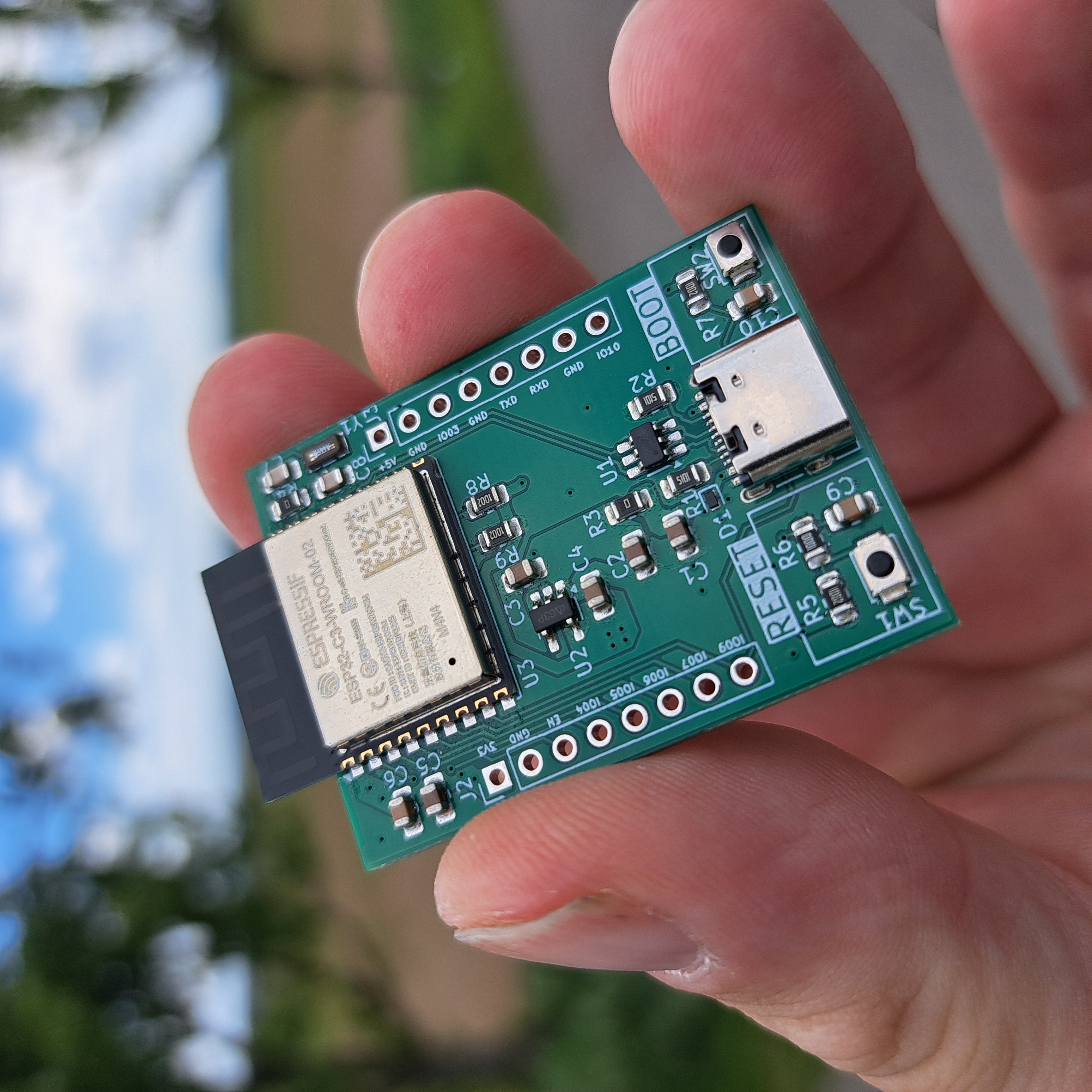
The Boards Have Arrived!
The PCBs finally arrived from JLCPCB and boy oh boy… they are beautiful.
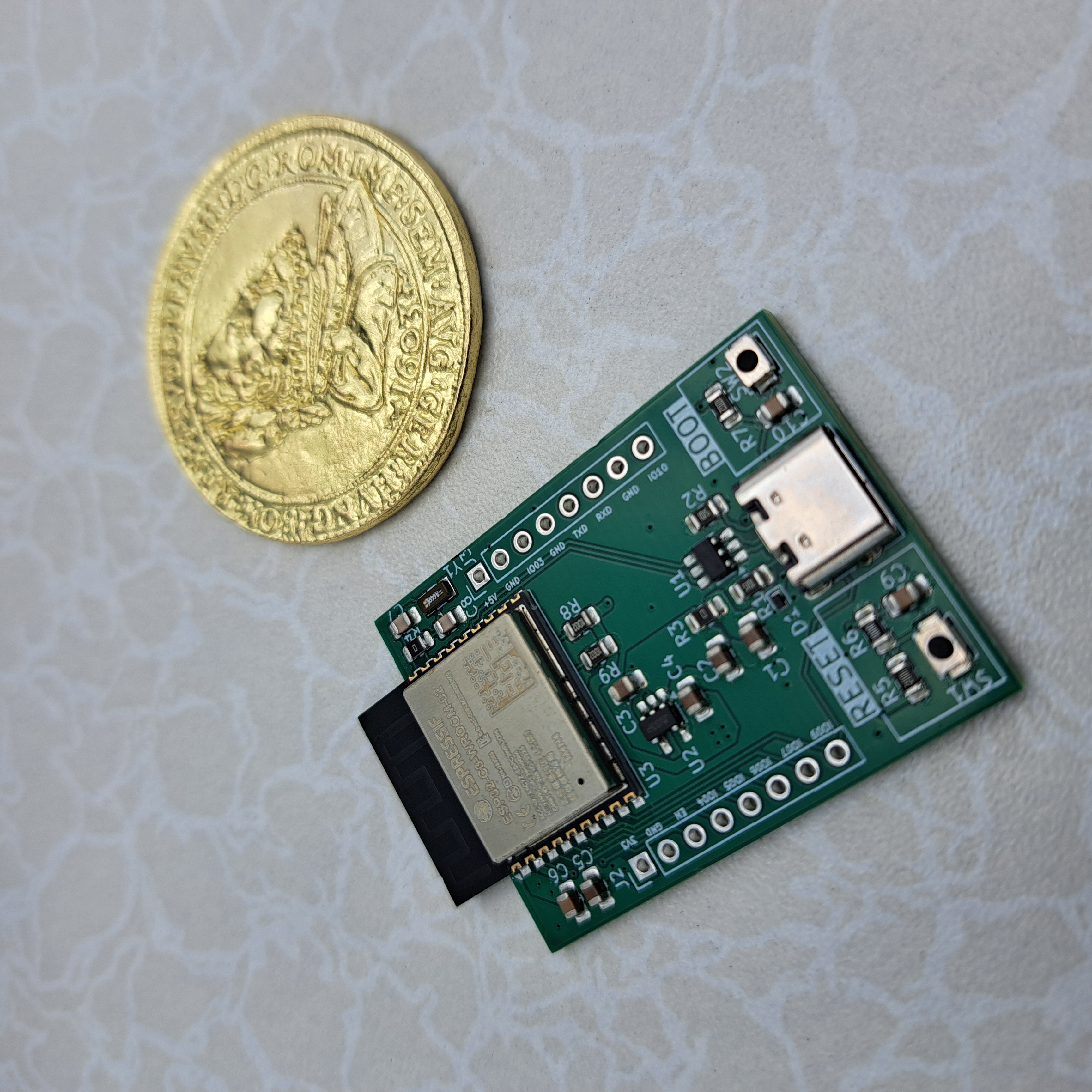
I was a little worried that the tiny labels around the GPIO headers (J2 and J3) would end up unreadable, but they turned out perfectly fine. Honestly, seeing a board you designed yourself become a real physical object never gets old.
The soldering quality is decent too. Some joints could probably use a bit more solder, heat, and time, but overall the assembly looks solid.
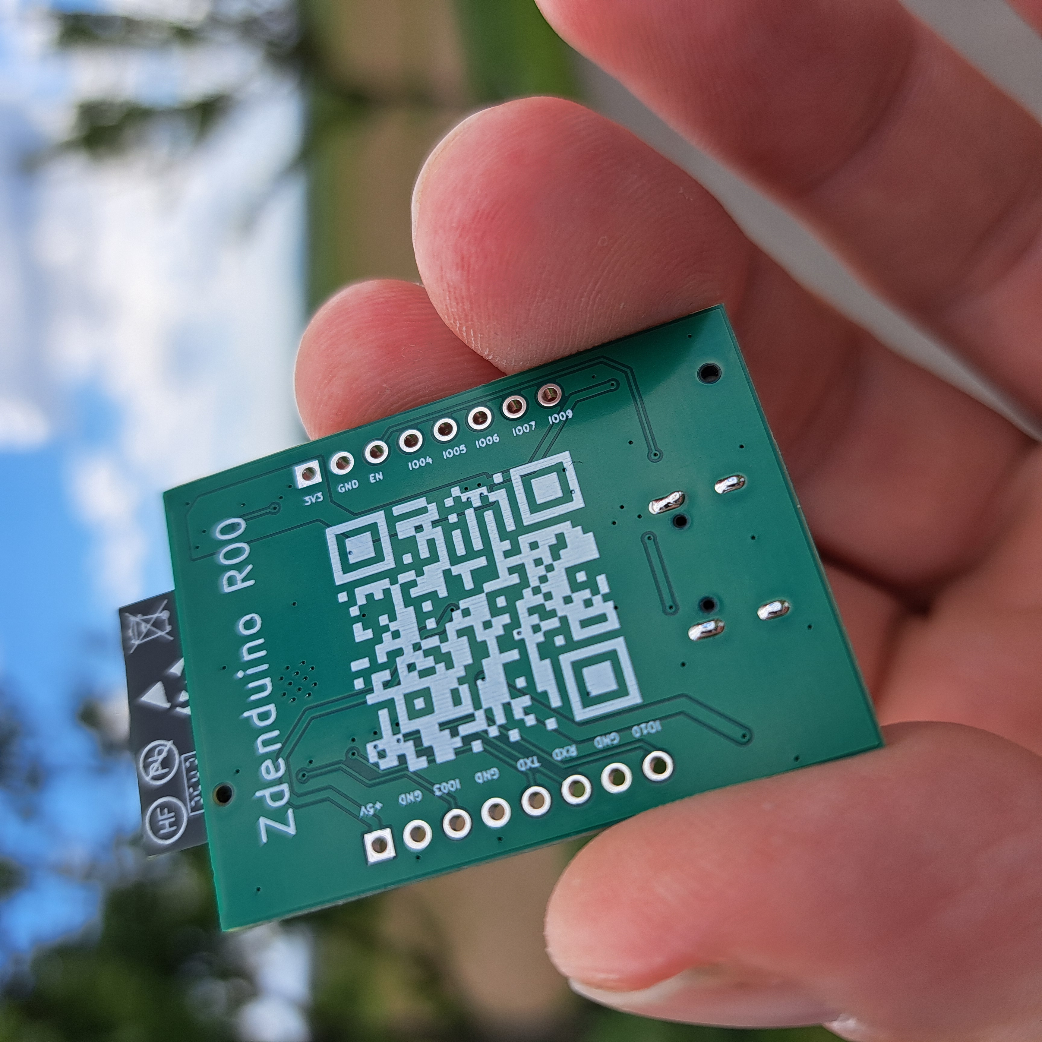
The First Power-Up Panic
The moment of truth had arrived.
I plugged the board into my PC and… my heart immediately sank.
Windows started rapidly playing the USB connect/disconnect sound over and over again. At that exact moment I was already mentally preparing for a full PCB re-spin.
“I messed something up.”
After a bit of searching, I discovered that the ESP32-C3 sometimes needs a little help entering the correct boot mode. Holding the BOOT button for a few seconds during connection solved the issue instantly.
The relief was very real.
Well… sort of.
Time for Testing
Since this board doesn’t have a user LED yet, the multimeter became my debugging companion.
I quickly threw together a simple blinking test program:
1
2
3
4
5
6
7
8
9
10
11
12
13
14
15
16
17
18
19
20
21
22
23
24
25
26
27
28
29
30
// ESP32-C3-WROOM
// Toggle GPIO 4, 5, 6 and 7 at 1 Hz
// (0.5 s HIGH, 0.5 s LOW)

const int pins[] = {4, 5, 6, 7};
const int pinCount = sizeof(pins) / sizeof(pins[0]);

void setup() {
  // Configure pins as outputs
  for (int i = 0; i < pinCount; i++) {
    pinMode(pins[i], OUTPUT);
    digitalWrite(pins[i], LOW);
  }
}

void loop() {
  // Turn all pins ON
  for (int i = 0; i < pinCount; i++) {
    digitalWrite(pins[i], HIGH);
  }

  delay(500);

  // Turn all pins OFF
  for (int i = 0; i < pinCount; i++) {
    digitalWrite(pins[i], LOW);
  }

  delay(500);
}
Simple enough, right?
Except Arduino IDE immediately rewarded me with a Compile Error.
After another quick round of searching, I realized the problem was my selected board profile. Using "ESP32 Dev Module" was wrong — the correct option is "ESP32C3 Dev Module".
That kicked off the classic Arduino experience:
- Updating board packages
- Waiting forever
- Clicking random menus
- Questioning life choices
Eventually, the upload process finally started.
And honestly? I absolutely love moments like this:
When the computer starts printing tons of technical-looking stuff into the terminal and it all actually makes sense.
1
2
3
4
5
6
7
8
9
10
11
12
13
14
15
16
17
18
19
20
21
22
23
24
Sketch uses 283952 bytes (21%) of program storage space. Maximum is 1310720 bytes.
Global variables use 14248 bytes (4%) of dynamic memory, leaving 313432 bytes for local variables. Maximum is 327680 bytes.

esptool v5.2.0
Serial port COM3:
Connecting...
Connected to ESP32-C3 on COM3:

Chip type:          ESP32-C3 (QFN32) (revision v0.4)
Features:           Wi-Fi, BT 5 (LE), Single Core, 160MHz
Crystal frequency:  40MHz
USB mode:           USB-Serial/JTAG

Uploading stub flasher...
Running stub flasher...
Stub flasher running.

Changing baud rate to 921600...
Changed.

Writing at 0x000555c0 [==============================] 100.0%
Hash of data verified.

Hard resetting via RTS pin...
Seeing all of this work on my own hardware was an amazing feeling.
The Second Panic
And then my heart sank for the second time that day.
Nothing worked.
I measured all the GPIOs and got seemingly random results:
- Some pins stuck HIGH
- Some LOW
- No blinking
- No logic
- Pure chaos
At this point I was already mentally preparing a “Lessons Learned” section for Revision 2.
After a small amount of panic (don’t judge), I asked ChatGPT for ideas.
Turns out…
I simply needed to press the RESET button after flashing. On NodeMCU this is not needed. But again, I’m not building NodeMCU.
And suddenly:
It worked.
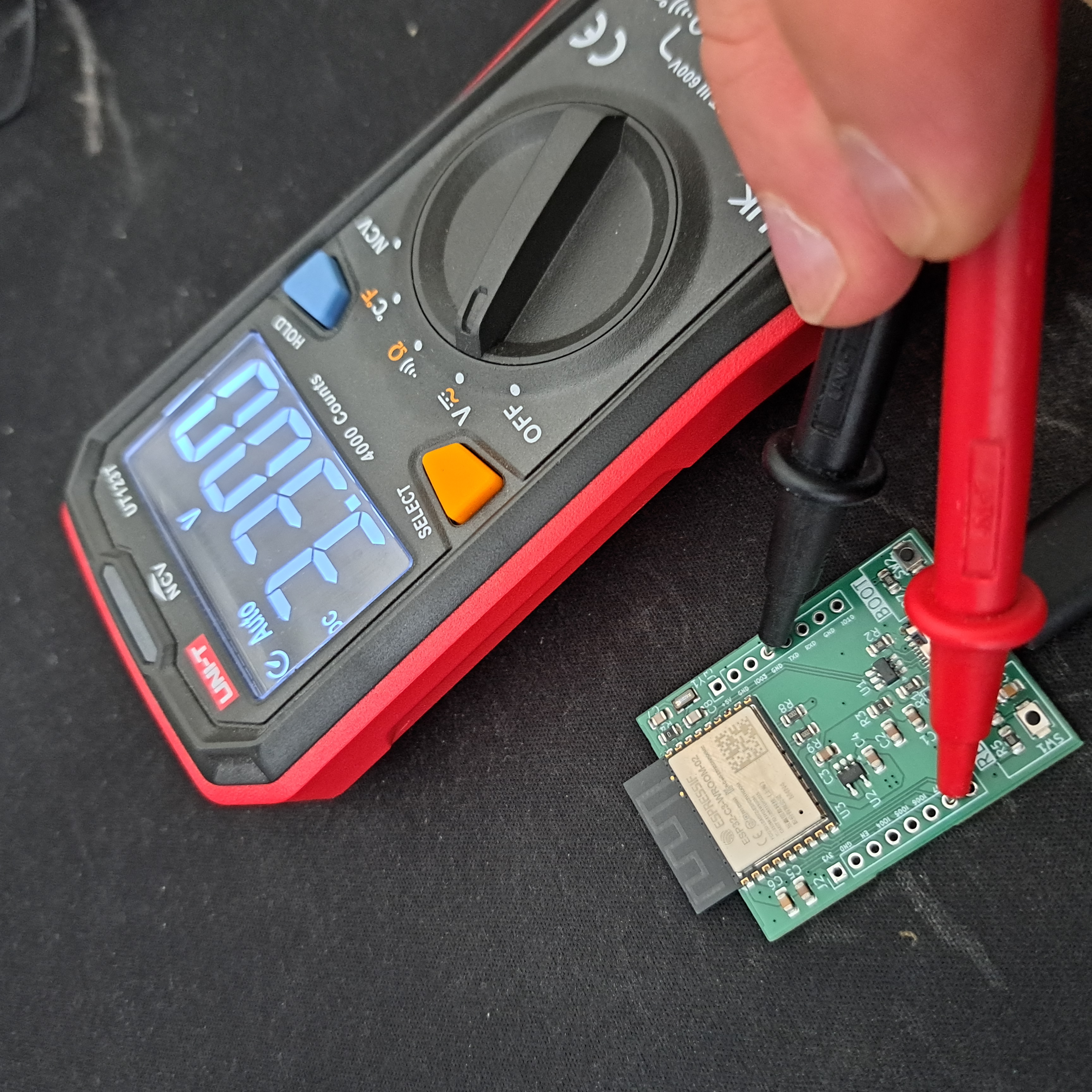
We all have our moments :D
To make the success finally visible, I connected a 100 Ohm resistor and an LED, and there it was: a proper, beautiful blink on my own board.
What Comes Next?
Right now my brain is basically bathing in dopamine and I already have a huge list of ideas for future revisions.
1. Hardware Improvements (R01)
There are definitely things I want to improve:
- Add a dedicated power LED
- Improve the GPIO connector layout
- Make the board easier to prototype with
I also want to experiment with castellated edges and through-hole style connectors similar to the Raspberry Pi Pico.
2. Shields, Hats & Breakout Boards
The next logical step is accessories.
The first one I really want to build is an:
- Industrial IoT Sensor Board
Something that demonstrates real-world use cases and turns Zdenduino into an actually useful platform.
3. Bigger and Better?
I’m also already thinking about a more advanced redesign:
- More analog capabilities
- Better power handling
- Improved RF layout
- Maybe more layers
Possible candidates:
- ESP32-C6
- STM32U5
- Something completely different?
I honestly don’t know yet.
But one thing is certain:
This project is far from over.
Final Thoughts
This was one of those projects where I learned an absurd amount in a very short time.
And despite the two mini heart attacks during bring-up, seeing my own custom ESP32 board successfully upload and run code was incredibly satisfying.
So stay tuned.
Because there is a lot more coming.