Connect Game - Part 2: Not All Power Sources Are Equal
Not All Power Sources Are Equal
Well… as the title suggests — lesson learned.
But more on that at the end.
Revision 1.1 – It Almost Worked
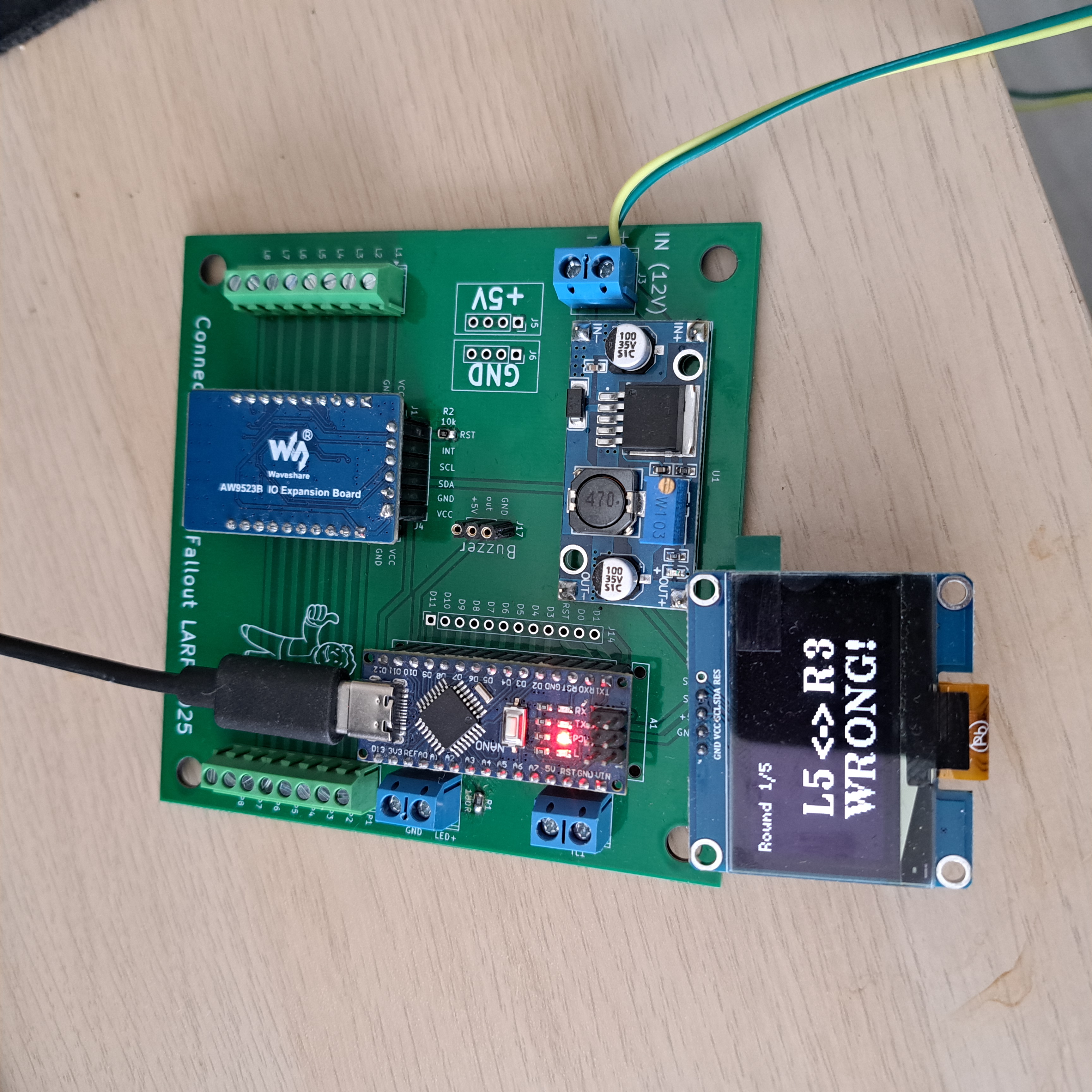
The updated PCB arrived from fabrication and, as always, the quality was ridiculously good for the price (around €4 for 5 pieces, shipping included… still hard to believe).
I didn’t waste any time:
- soldering iron on 🔥
- some chill music in the background 🎧
- and straight into assembling the board
To be fair, there wasn’t that much to populate — it’s essentially a slightly smarter breakout board.
I flashed the firmware, rebooted the Arduino and…
👉 It worked.
Big win.
…for about a minute.
The Weird Buzzer Problem
Everything was fine when powered over USB-C (5V).
But the moment I switched to 12V input (through a step-down converter), things went sideways:
- the buzzer started emitting a high, ugly, constant buzz
- it ignored any attempt to control it via software
- pin D12 behaved correctly… but the buzzer clearly didn’t care
At that point it was obvious:
👉 this is not a software issue
Hardware Fix
So I went the classic route — local electronics shop and a bit of experimentation.
I picked up:
- BC547 (NPN transistor)
- a few resistors
- some capacitors
…and built a quick test circuit on a breadboard.
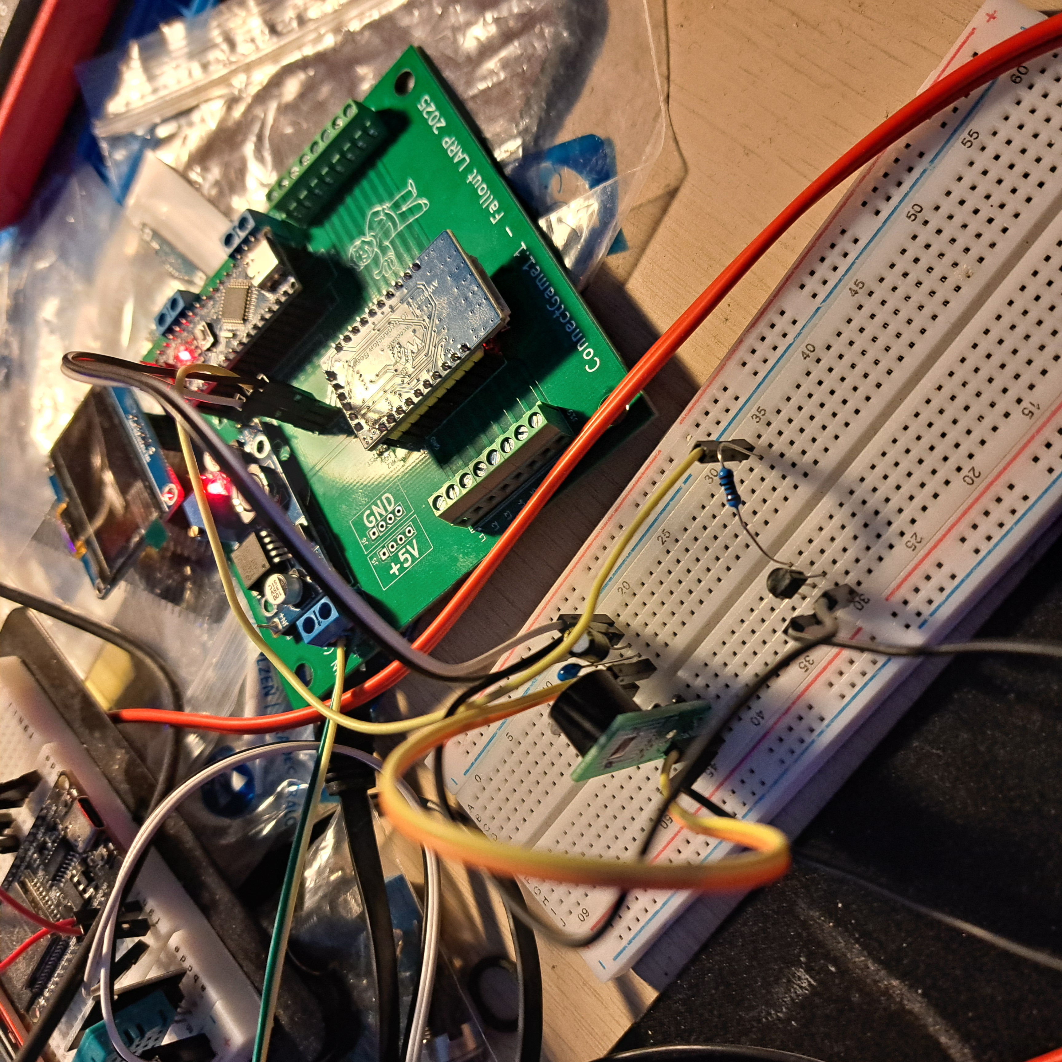
And just like that:
👉 it worked perfectly
- no humming
- clean switching
- buzzer only active when it should be
Honestly, it felt a bit like magic.
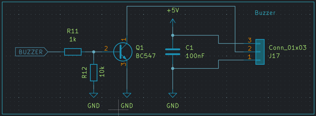
If the breadboard spaghetti isn’t exactly readable, here’s the schematic:
Why This Happened
So what was going on?
When powered from USB (5V), the system was relatively clean:
- stable voltage
- low noise
- Arduino directly driving the buzzer
However, when switching to 12V → step-down converter → 5V, a few things changed:
1) Electrical Noise
Cheap (or even decent) buck converters introduce:
- voltage ripple
- switching noise
This noise can leak into the control signal and cause the buzzer to behave unpredictably.
2) Insufficient Drive / Floating Behavior
Driving the buzzer directly from a GPIO pin can be problematic:
- limited current capability
- undefined states during boot/reset
- susceptibility to noise
3) No Proper Switching Stage
Without a transistor:
- the Arduino pin is doing everything
- there is no isolation between logic and load
Why the Transistor Fix Works
Adding the BC547 solved all of this:
- the Arduino now only drives the base (tiny current)
- the transistor handles the actual switching
- the buzzer gets a clean, stable signal
- optional capacitor helps smooth out noise
👉 In short: proper signal isolation and amplification
Revision 1.2
With that figured out, it was time to:
- update the schematic
- fix the PCB design
- export new Gerbers
- and send it back to fabrication
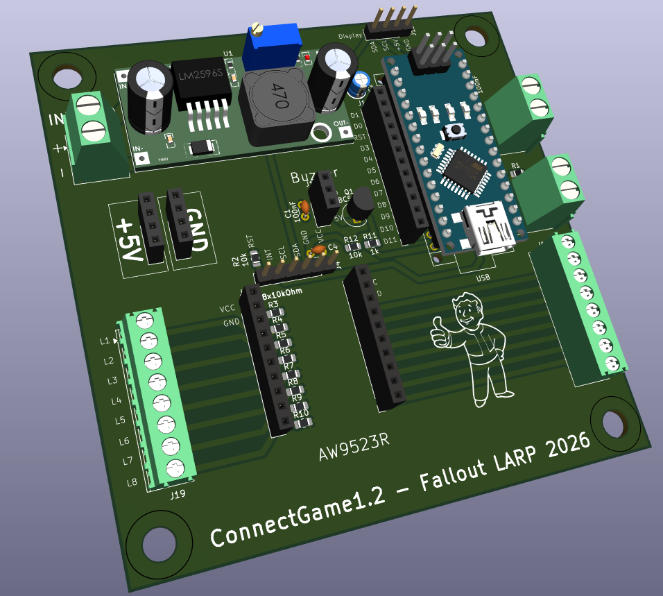
Here’s the updated 3D model of revision 1.2:
And now…
👉 we wait again 😄
What’s Next?
If everything goes well (🤞):
- test the new boards
- design a proper enclosure
- and finally hand the device over for the LARP event
Lesson Learned
Not all power sources are equal.
- USB power is clean and predictable
- step-down converters can introduce noise and instability
- GPIO pins should not directly drive loads like buzzers
👉 Always use proper driver circuitry (transistor, MOSFET, etc.)
Stay tuned for Part 3.