ESP32 Weather Station - First PCB (Rev0)
ESP32 Weather Station - First PCB (Rev0)
After a bit of breadboard chaos and cable spaghetti, it was time to move to something more permanent. Meet Rev0 — the first PCB for the ESP32 Weather Station project.
🛠️ Specs & Design Philosophy
- Designed in KiCAD
- Ordered from jlcpcb.com
- Dimensions: 100mm × 100mm — the largest possible for their standard pricing
- ✅ Leaves space for wide traces, labels, and comfort
- ✅ No surcharge for going to full 100×100
- Color: Black
- Because… elegance 😎
- All unused GPIOs are broken out to pin headers for future expandability
- Includes a QR code linking directly to the GitHub repo:
ESP32-Mark0 GitHub- ⚠️ Small issue: The QR code is technically in the pad layer due to a layering problem during export. It should be in the silkscreen layer.
🧠 Breadboard Lessons → PCB Decisions
In the previous post (Love/Hate with Breadboards), I talked about how fragile breadboarding can be.
So for this board:
- I chose precision pin sockets to ensure the ESP32 DevKit board sits firmly in place
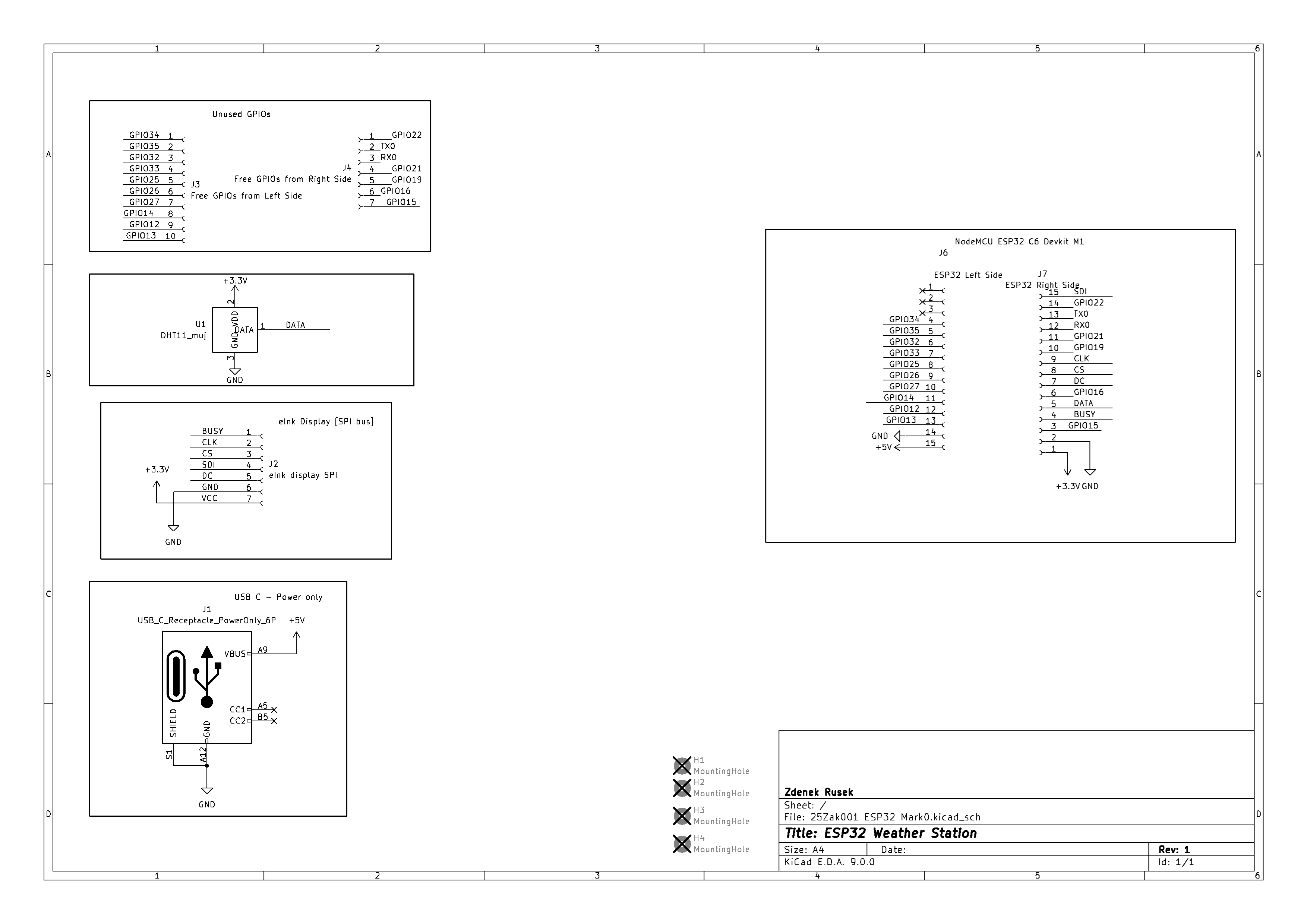
- Since Neven (the ESP32 board manufacturer) doesn’t publish a proper footprint, I manually added two rows of 15-pin female headers in the schematic
📐 Schematic
Here’s the schematic for Rev0:
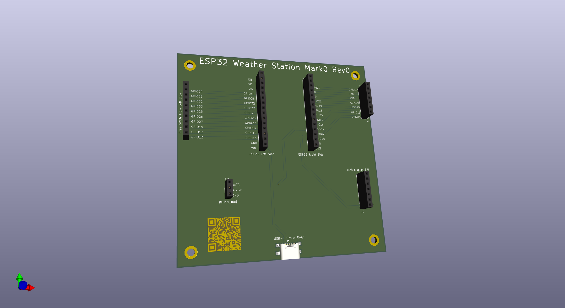
🧱 3D Render
Below is the 3D view of the board rendered directly from KiCAD:
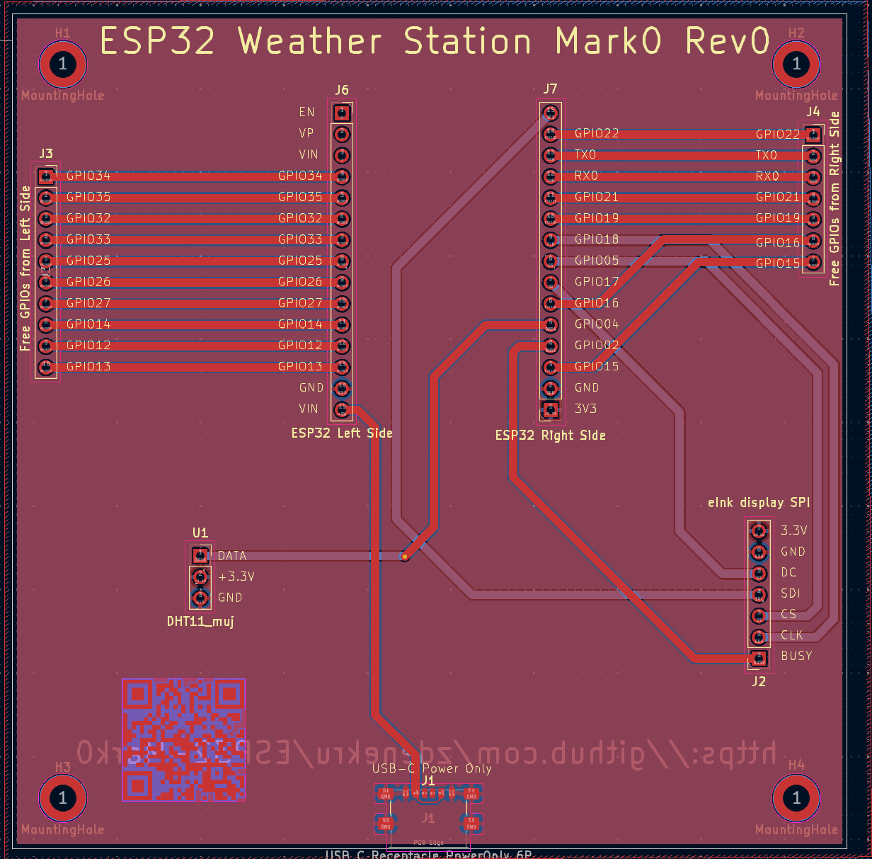
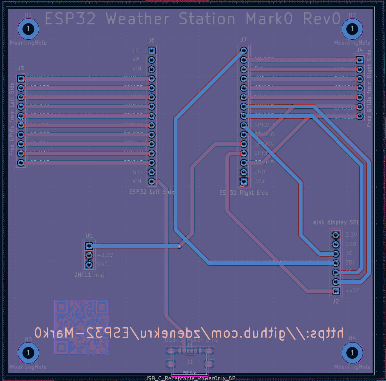
🔳 PCB Layers
🔝 Top Layer
🔙 Bottom Layer
🚀 Next Steps
Waiting for the PCBs to arrive! Once they’re here, I’ll do assembly, first boot, and then finally power it up without worry of faulty breadboards’ jumper wires.
Stay tuned for a build log once Rev0 is in hand!
This post is licensed under CC BY 4.0 by the author.